Physical tone matrix

June 29th, 2010

Inspired by Andre' Michelle's Tone Matrix flash applet I decided to make a physical version - i.e. a box with buttons, flashing lights and knobs to turn. I wanted 16x16 - the Bliptronic 5000 just doesn't have enough lights. All the existing 16x16 equivalents were more money than I wanted to pay: A Tenori-on costs something like $1000. Four Bliptronic 5000s cost $200. A monome two fifty six costs $1400. I was thinking more along the lines of $50. Besides which, I thought to myself, it would be fun to make it myself.

I decided to base it around the ATmega328 microcontroller used in the Arduino, after reading how easy it is to get started hardware hacking with the Arduino. Yes, I know a Cortex M0 is a cheaper and more powerful chip, but I didn't know about these until I'd already started with the ATmega328. Also, they're more difficult to solder.

Because of my assembly programming roots, I wanted to push the CPU to its limits. Sketching out the core audio and video assembly routines, I realized that with the Arduino's 16MHz clock rate, I could do 16 channel PWM audio at a sample rate of 15.625KHz (i.e. a sample every 1024 cycles) with a 256-element 8-bit waveform and arbitrary volumes and frequencies for each channel. At the same time I could control a 16x16 LED matrix with a refresh rate of 61Hz (line rate of 976Hz) with each individual LED having an independent brightness (duty cycle of 0-16 sample periods per frame, i.e. up to 1/16 in 1/256 increments) using 32 bits of shift registers and the SPI lines (at maximum speed it takes a significant number cycles to output so many bits, so this is interleaved with other code). Unfortunately (because of the large gamma of LEDs) only a few of these are distinguishable. With all of this going on in the background (written in heavily optimized assembly language) I still had enough spare CPU cycles to do some interesting foreground things.

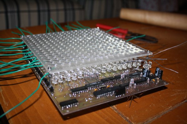
The next problem was how to make the switch matrix and LED matrix. I thought about buying 4 Bliptronic 5000s and tearing them apart, or using sixteen Sparkfun 4x4 button pads with PCBs, but both of those options cost more than I wanted to pay. The cheapest high-brightness LEDs I could find cost $0.06 in quantity from Mouser, giving a screen cost of $15.36 - much more like it. (Even cheaper prices are possible in greater volumes from Transistor Parts Wholesale). I think this is the cheapest way of making a 6"x6" screen.

I had trouble thinking of a way to set up 256 switches over the LEDs without obscuring them or spending too much, until I remembered an effect I had noticed messing about with transistors years ago - you can make a touch switch out of a couple of transistors arranged in a Darlington configuration. I could arrange them in a matrix like the LEDs so that the only per-switch cost was a couple of small sections of wire. This could be threaded through an acrylic sheet which would serve a dual purpose - to diffuse the LEDs and to hold the switch wires. I originally thought I would have 4 solder connections to the PCB per switch, but then I realized that that would be too difficult to solder and that it would be better to just connect my switch matrix at the edges.

The row strobes used for the switches are the same as the ones used for the LEDs, and the column strobes are accomplished with a couple of 8-bit analogue multiplexers, so that only two Darlington pairs are needed for the entire matrix (the final thing includes a third for a "menu" switch). One tricky thing here turns out to be the capacitance - since the finger resistance is about 10 megaohms and we move on to the next switch 15,625 times per second, we need a capacitance of no more than 6pF, which one gets from having just a few centimeters of wire in close proximity. Fortunately that's just for between the multiplexer and the Darlington pair - the switch matrix itself only changes configuration 976 times per second so we can get away with a larger capacitance. Even so, I think this is at about the limit of practical resolution for such a matrix. It proved necessary to put a capacitor between the base of the Darlington pair and ground to counteract the admittance of the switch matrix and reduce its sensitivity.

I used a double sided circuit board (in order that I could have LED row wires on one side and column wires on the other), but I think if I were doing it again I'd use a single sided board and just connect the columns by soldering the LED anodes to straight pieces of wire laid across the top of the board. Between aligning the two sides correctly, doing very fiddly soldering under the components on the top side, making lots of vias and not being able to test most of the board until almost everything was soldered (due to some of the component legs acting as vias) it was more trouble than it was worth.

For debugging purposes, I made a connector so that the device could be connected via an Arduino and a USB port to a computer. There is essentially a "non stop" debug interface built into the program - as it's running, one can send commands over the ATmega's UART to peek and poke memory.

The sound quality isn't great at the moment - it was okay on the breadboard but the breadboarded version of the circuit had a "screen" of only 4 LEDs. With 256 LEDs the ripples on the power supply are much bigger and there's a lot of noise on the speaker when lots of the pixels are lit. I did have some decoupling capacitors in the circuit but I drastically underestimated the amount of capacitance I would need - I'll replace the capacitors with larger ones after my next Mouser order.

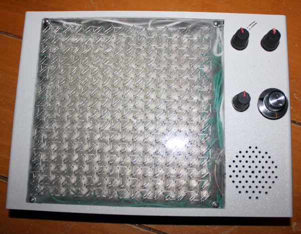
The final design has 4 potentiometers: tuning, volume, decay/sustain and tempo.

The software I wrote for it has lots of features:

  • Random mode: after each cycle through the pattern, extinguish one LED at random and light another at random. This keeps the pattern varying.
  • Game of Life mode: after each cycle through the pattern, transform the pattern according to Conway's rules.
  • Various waveforms: choose from sine wave, square wave, triangle wave (which unfortunately sounds indistinguishable from the sine wave) or two different types of random noise. There are also a couple of different waveform editors so you can make up your own.
  • Tuning editor: the default scale is pentatonic but you can change it to use whichever frequencies you like.
  • Overrides for decay, tempo and tuning so they can be set via either digital or analogue controls.
  • Microtone mode: sets the matrix up as a 256-key keyboard spanning 7.5 octaves with a 34-TET tuning. LEDs corresponding to the notes of the C major scale are lit (which makes a pretty pattern). Because of the way the switch matrix works, only chording within a row or a column is possible without introducing spurious notes.
  • Saving and loading patterns, waveforms, tunings and other settings to/from EEPROM. Unfortunately there is a bug in the software at the moment which causes it to crash after saving.
  • Multi-pattern mode: loads a new pattern from EEPROM each time the current one finishes.
  • Sync in and sync out sockets: I believe these should be compatible with those on the Bliptronic 5000, but I don't have one to try it out with.
  • Ability to have less than 16 beats before repeat (for making rhythms with different time signatures).
  • Just for fun, a red/green/blue LED triplet. This displays a hue corresponding to the beat currently being played within the pattern. It seems totally frivolous, but was quite handy for debugging this problem when the program was so broken that the serial code didn't even work.

There are a few more that I've thought of but haven't implemented yet. Almost half the flash is unused currently - enough to add a few games as well.

The machine runs great on 4 AA batteries (6.52V according to my multimeter) or from a 5V supply. I think the ICs are rated up to 15V or so, but the LED current limiting resistors would need to be increased to use a higher voltage.

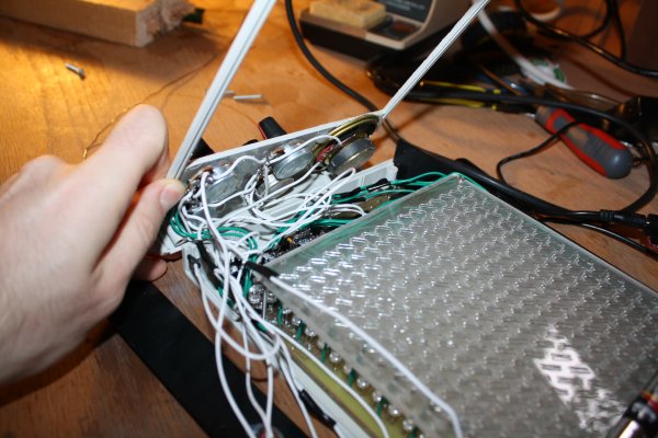
One tricky thing about making this is threading all the wire through the acrylic sheet - I used fairly thick wire (22 AWG) for strength so I had to be careful to avoid kinks and make sure the wire was tight each time. Using thinner wire would be easier but flimsier. I imagine that it could be mass produced more easily using techniques similar to making a double sided PCB (i.e. using tracks and through-hole plated vias instead of a solid piece of wire).

In the end the parts cost for this adds up to $64.83 (not counting time, broken tools and supplies like solder, toner, paper, acetone, steel wool, glue and ferric chloride), though not all of the parts I actually used were bought new (I salvaged the speaker and a capacitor from an old alarm clock, for example). It could probably be mass produced for significantly less (particularly the case I imagine).

The schematics, source code, PCB layout and parts list are available here. If you make a copy or derivative I'd love to hear about it.

Volatile registers in GCC

June 14th, 2010

When writing microcontroller code in assembler, it's nice to be able to keep some commonly used variables in registers. The 8-bit AVR devices in particular have a nice big set of registers, most of which are rarely used in compiled code. Usually it's a waste of time to write all the code in assembler, though - it's much better to write the non time-critical bits in C, compile them with GCC and then link with the assembly code bits.

When accessing the register variables from the C code, the natural thing to do is just to make a global register variable:

register uint8_t frame __asm__ ("r3");

That has two effects - it allows you do access the variable as if it were a normal variable:

void initFrame()
{
    frame = 0;
}

And it prevents the compiler from using r3 for something else (though one also has to be careful that the register isn't used by any other linked in libraries, including the C library and the compiler support functions in libgcc).

The trouble comes when you try to read those register variables. If optimizations are turned on, then the following code might just be an infinite loop:

void waitForFrame(int frameToWaitFor)
{
    while (frame != frametoWaitFor);
}

The compiler hoists the read of frame outside the loop, and never sees the updates. If frame was a normal variable we could fix this just by adding volatile, but using volatile with a register variable doesn't work. This seems odd until we think about what volatile actually means. A read from or write to a volatile variable is considered an observable effect (like doing IO) so the compiler won't optimize it away. But the compiler has no concept of a "read from" or "write to" a register - registers are just used or not used and the optimizations around them are unaffected by the notion of volatile.

There is a reasonably easy and not-too-invasive way to fix this, though, through the use of inline assembly. If you write:

#define getFrame() ({ \
    __asm__ volatile ("" : "=r"(frame)); \
    frame; \
})
 
void waitForFrame(int frameToWaitFor)
{
    while (getFrame() != frametoWaitFor);
}

The compiler will treat the "" as a block of assembly code which writes to r3 and which has unknown side effects (so that it can't be hoisted out of a loop for example). The code doesn't actually do anything (so the generated code won't be adversely affected) but it essentially provides a read barrier to the register. Unfortunately you can't use getFrame() to write back to frame, so to increment it for example you have to do frame = getFrame() + 1; but that's actually kind of helpful because it makes the possibility of a race condition (for example by an interrupt routine also incrementing frame at the same time) more obvious.

Improved GPU usage for fractal plotter

November 1st, 2009

I've been tinkering with my fractal plotter again. One thing that annoyed me about it was the pauses when you zoomed in or out past a power of 2. I thought this was due to matrix operations until I did some profiling and discovered that it was actually dilation (both doubling and halving) of the "tiles" of graphical data to which squares are plotted and which themselves are painted to the screen.

This is work that can quite easily be done on the GPU, without even having to resort to pixel shaders, by using the ability to render to a texture. Here is the result and here is the source. In order to do this I moved all the tiles to video memory (default pool instead of managed pool) and used ColorFill() to actually plot blocks instead of locking and writing directly to textures. All this adds up to much more CPU time available for fractal iterations.

Another change is that instead of an array of grids of tiles, I've switched to using a grid of "towers" each of which is itself a tile and can point to 4 other towers. This simplifies the code somewhat.

There is still some glitchiness when zooming but it is much less noticable now.

This reminds me of something I meant to write about here. When I originally converted my fractal program to use Direct3D, I figured that locking and unlocking textures was probably an expensive operation so rather than locking and unlocking every time I needed to plot a square, I kept them all locked most of the time and just unlocked them to paint. However, it turns out that this "optimization" was actually a terrible pessimization - now all the tiles were dirtied each frame and had to be copied from system memory to video memory for each paint, and because of the locking nothing else could happen during that time. I was able to get a big speed up by locking and unlocking around each plot operation - that caused only the parts of tiles that were actually plotted on to be dirtied. It just goes to show that when optimizing you do have to be careful to actually measure performance and see where the slow bits really are.

Wireless mice

October 31st, 2009

This is fascinating. I wonder how long it will be before people are implanting tiny devices into mouse brains that receive commands from the internet via the cellular networks and transmit video and audio back, so that the mice can be driven around by remote control and used to spy on people and things.

Fall foliage

October 30th, 2009

Inspired by this XKCD comic:

I made this:

And this, going in the opposite direction:

Rotating fractal

October 29th, 2009

Last year, I wrote about a way to make rotating fractals. I implemented this and here is the result:

The equation used was z <- z1.8 + c, and the branch cut varies from 0 to ~10π.

What are all those pins for?

October 28th, 2009

I recently built myself a new computer using an Intel Core i7 920 CPU. This CPU has more pins (well, "lands" actually, since they are just flat conducting areas that touch pins in the socket) than any other yet produced, 1366 of them to be precise. I was wondering why so many were needed, so I grabbed the datasheet and made a map:

Power:
     VSS
     VCC
     VCCPLL
     VTTA
     VTTD
     VDDQ

Memory:
     DDR0 data      other
     DDR1 data      other
     DDR2 data      other

Other:
     QPI data      other
     Other
     reserved

Idle speculation follows (I don't have any background in CPU or motherboard design):

The pins roughly divide into six sections: two for memory data, one for other memory-related signals, one for power, one for the QPI bus and one that is mostly reserved.

That there are a lot of power pins is not surprising - this CPU can use as much as 145A of current, which is enough to vaporize any one of those tiny connections, so it has to be spread out amongst ~300 of them for each of power and ground. Having two very big pins for power would probably make the mechanical engineering of the CPU much more difficult and would push the responsibility for branching out that power onto the CPU, whereas it is better done by the motherboard.

It's interesting that the ground lands are mostly spread out but the power lands are mostly together. I'm not sure why that should be - I would expect them both to be spread out. Perhaps the 8 or 9 big groups of VCC on the north edge each correspond to a single "power line" on the motherboard (and hence are grouped together) while the distributed ground lands are needed to supply electrons for the signal lands.

Three DDR3 channels also use a lot of lands - 192 for data alone and almost as many again for addresses, strobes and clocks.

Another thing that surprised me is that there are so many reserved lands (~250 of them). Initially I thought that this was because the socket was designed before the designers knew how many pins they would actually need, so they made sure to design for the absolute maximum. However, a good chunk of the reserved lands are used by the Xeon 5500 CPUs, which use the same socket - in particular for memory error detection/correction and the second QPI bus (which is presumably in the northwest corner).

Edit 14th July 2013:

Here are some more nice pin maps.

A trip around the cardioid

October 27th, 2009

Take a point that moves around the edge of the main cardioid of the Mandelbrot set, and plot orbits with values of c close to that point. You end up with this:

It can be thought of as a sequence of cross-sections of the Buddhabrot.

Guns would not be useful against a tyrannical government

October 26th, 2009

Gun enthusiasts in the US often claim that it's important that citizens can bear arms in order to protect against a government that has become tyrannical. However, I don't think that argument really holds water - it seems to me to be a rather outlandish fantasy that a group of citizens could overthrow the government.

For a tyrannical government to have any effect, the power structures between it and the people would still have to be largely in place - in particular, the military and the police would have to be still taking orders from the government. But any given individual citizen gun-owner would be vastly outgunned by the military, which has access to far more powerful weapons. So an extremely large number of individual gun owners would be needed. I have no idea how many, but it would probably have to be several times the size of the US standing army, so in the multiple millions. But if the government failed to convince all those millions of people that it is not a tyranny, how could it have convinced the military and the police?

A far more useful tool against tyranny is an educated and well-informed population. If you can't pull the wool over the eyes of the people, you also can't pull the wool over the eyes of the agencies enforcing the will of the government. For this reason it's far more important that people get accurate and unbiased news than it is that guns are kept legal. If a tyrannical government does emerge (and there are some indications that it already has) it will be because the people have been lied to, not because they don't have enough guns. And frankly, the state of most mainstream news is so bad that this does seem to be a real danger.

It's very important that we all have a good understanding of current affairs. To do this we should:

  • Avoid getting our news from just one source, or from sources with similar bias.
  • Check the facts - follow up on the references and follow the chains of evidence back to the source wherever possible.
  • Know our fallacies
  • Disregard news sources that rely on unsubstantiated rumour ("Some say that...")
  • Be particularly wary of religious arguments, since in religion not only is objective evidence lacking, but searching for it is actively discouraged.

People are colonies

October 25th, 2009

When I first learned that the human body was made up of trillions of cells I was fascinated. These cells are almost like small organisms themselves - they grow, reproduce, consume and respond just as the organism itself does. It's almost as if the human body is a colony, not just an individual. In fact, it seems very likely that the first multicellular organisms were actually colonies of individuals which stuck together and began to evolve as a group, not just as individuals.

Another fascinating fact that I learned recently is that there are more bacterial cells than human cells in a human body - though they are much smaller they are about 10 times more numerous. It's sort of like how we keep animals of different species like cows and chickens in our macroscopic communities.

Even our human cells aren't "pure human" - they contain mitochondria which have their own DNA and almost certainly evolved from a separate line if you go back far enough in history. It's almost like life is fractal (though the self-similarity doesn't descend infinitely).

That makes me wonder if colonies act as individuals on a much larger scale. If we colonise the universe could we end up with societies that are complex enough to have an awareness of their own? Could we ever, as individuals, become aware of this awareness? Presumably (because of the speed of light) such awareness would be much slower than ours and generations could be born and die in the time it takes for a single thought to happen in on the "higher level". However, because we (unlike our cells) are intelligent beings, we could presumably read the writings that such a being had made over the course of history. Such a being would be a God, in a sense, as it would transcend us, but wouldn't necessarily be omnipotent, omniscient or kind, and certainly wouldn't have created the universe.