Archive for June, 2010

Physical tone matrix screen construction details

Wednesday, June 30th, 2010

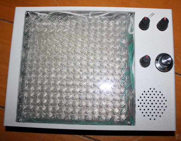
I think the most unusual thing about the physical tone matrix I posted about yesterday is the screen - I hadn't seen one like it before I made it, and having made one I now know why - they're very fiddly to make. I'd like to go into some more details about how it is made and how it works.

Step 1 is to cut out a 6" square piece of 1/8" thick acrylic. I bought a 12"x24" piece from Delvie's plastics (the cheapest shipped price I could find for such a small quantity), which is enough for 8 such screens (though I doubt I'll make another 7 since threading the wire takes so long - I hope I'll be able to make something else fun out of the rest, though). Cutting this stuff is really easy - just score it a few times with a knife and a straightedge where you want it to break, clamp it to a table so that the scored line runs along the edge of the table and then push down hard on the bit that protrudes over the edge of the table - it'll break cleanly along the scored line. Leave the backing paper on for now.

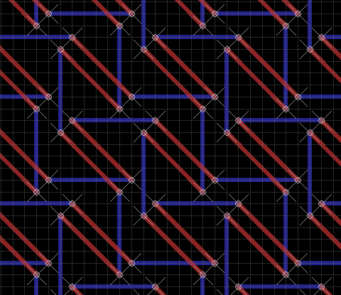
Step 2 is to drill the holes. I deliberated a bit about the hole pattern to use. I originally thought of threading the wires just horizontally and vertically, so that the switch was formed at the place where the two wires "cross over" (but don't quite touch) in the following picture (red is top, blue is bottom):

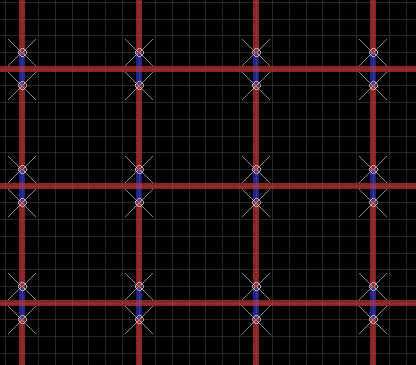
But then I decided I'd rather have the central point of the switch not have wire over it, so that the LED would be able to shine through at that point. I also realized that I'd be able to make the switches longer (and therefore easier to press) if the wires were arranged diagonally and fairly close to each other. Working backwards from where I wanted the wires to be on the top, I came up with this pattern:

This requires about 67 feet of wire altogether - because of the zig-zagging, each horizontal and vertical wire is about 15" on the matrix itself, with 2" spare on the top, left and right sides and 14" spare on the bottom to connect to the PCB. Use 22AWG solid-core hook-up wire - this should work nicely.

Here is a page showing where all the holes need to be drilled. Print this out and glue it on to one side of the acrylic sheet. Use a drill press to drill all 1,024 holes. I used this which is the cheapest one I could find. It's a bit flimsy but good enough for the purpose (as well as for PCBs, which is what it's meant for). It doesn't quite have enough clearance to reach the center holes if you put it together in the obvious way, but it does come with an attachment which lets you move the drill further away from the metal bar, if you jam a piece of plastic or something in the gap. I used these bits which seemed to work fine. The positioning doesn't have to be perfect but the closer the better. I think I used a number 68 drill bit or thereabouts - make sure your wire fits through the first hole you drill before drilling the rest. The plastic swarf from the drill will accumulate under the glued paper a bit but that doesn't really matter.

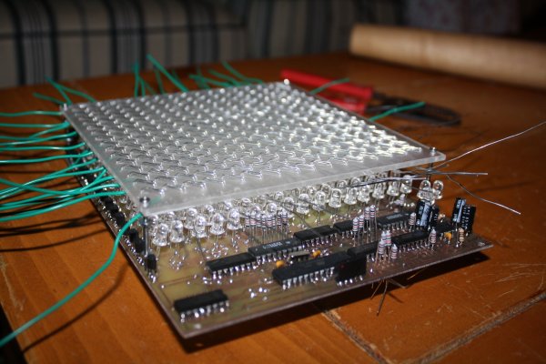
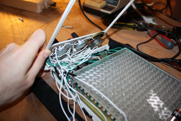
While you've got the drill press handy, make a hole of ~2mm diameter in each corner for the screws to hold it onto the PCB. The way I built it, the switch matrix is screwed to the PCB using 1-1/2" long screws and then the PCB is screwed to the bottom box, so the entire thing is rigid (the top of the box also screwed to the bottom of the box - only these screws need to be removed to change the batteries). Choose the positions of these holes carefully, since you will need to make holes in the same position in the PCB.

Step 3 is to remove the backing paper and sand the acrylic on the bottom side using a piece of sandpaper. Shine an LED through it to make sure it's diffusing properly. If you don't sand it the screen will have a very narrow viewing angle (depending on the LEDs used - cheap high brightness ones tend to have a very narrow viewing angle though) and when you can see them they will dazzle you. I think I used a #100 sandpaper or thereabouts - I don't think it matters much but try on a scrap piece first if you're worried. An orbital sander will probably get you a more homogeneous finish, but I just did it by hand (you can see the swirl patterns I made if you look at the screen very closely).

Step 4 is to cut and strip the wire. Cut 16 lengths of wire 19" long and 16 lengths of wire 31" long. Avoid kinking/bending the wire at this stage, to the extent you can. Use wire strippers to strip of all but 2" of insulation from the 19" lengths and all but 14" of insulation from the 31" lengths. You'll need to do this about 6" at a time. You might need to grip the 2" piece of insulation with pliers when stripping the last bit, otherwise you'll remove the wrong bit. Keep the pieces of insulation for step 6.

Step 5 is to thread the wire. Take each piece of wire in turn and thread it into the acrylic, starting at the bottom (31" sections) and the right (19" sections). Push the wire in so that the remaining insulation is right up against the bottom of the acrylic. Follow the pattern carefully - the top wire of each switch goes horizontally and the bottom goes vertically. Bear in mind that the pattern alternates each row, so if you start with the top one in the first row, you'll start with the bottom the second. The PCB has holes for soldering the top and left sides directly underneath the switch matrix, so make sure you pick the alternating pattern that gets it to line up. Make sure none of the wires touch each other - you can always pull them apart slightly with needlenose pliers if they do.

There is a bit of a knack to getting the wires flat and tight with no kinks. Here is how I did it. Suppose you have one segment threaded on the bottom and you're doing the next one on the top side.
a) Thread the loose end of the wire through the next hole. Pull it through. As you are doing so, make sure the wire is in the plane that is perpendicular to the acrylic sheet and that passes through the two holes. If the wire starts to twist over, adjust it so that it is back in this plane. If you don't do this, you'll get a kink in the wire when you pull it tight, which makes it difficult to get it to go where you want it to.
b) get a flat piece of metal (like the side of a pair of pliers) and push against the threaded segment on the bottom. This will prevent the bottom segment from being pushed up in the next step.
c) get another smaller flat piece of metal (like the end of another pair of pliers) and push against the newly threaded segment on the top. Start pushing at the "old" end (bending the wire into a right angle) and work your way along to the "new" end until it's totally flat against the acrylic sheet. If you don't do this there will be slack in the wire which will cause the switches to move when you touch them.

It gets more difficult once you get more of the wires in place, because you've got to navigate around the protruding ends with your flat edges. It might make it easier to do the outermost wires first and then work in towards the middle, but I didn't think that far ahead.

Once I got into practice, it took me about 20 minutes to do each wire, so about 11 hours of threading altogether (this is why I'm not planning to make any more). It's not too bad if you do a couple a day for a couple of weeks - one can carry on a conversation or watch TV at the same time.

Step 6 is to re-insulate the uninsulated loose ends. Cut 1" sections of insulation from the leftovers from step 4 and push them back onto the ends of the wire. If there are any bends or kinks in these parts of the wires you'll have to straighten them out with pliers first. Twist the insulation slightly as you push it back on and it'll go on more easily. This will help avoid short circuits when the circuit is partially assembled and you're testing it.

The switch matrix works by strobing each row and then testing each column. The rows are connected to the output of the "row" 74HC595 shift registers. They are connected via 10K resistors so that if something metal touches the switches they won't cause short out anything. The "active" row (which changes about 1,000 times per second) is brought to logic high (+5V), the others to logic low.

The switch columns are connected (again via 10K resistors) to 74HC4051 analogue multiplexers so that the microcontroller can specify (with three output bits) which of the 8 columns in each half of the matrix it wants to read. This column selection changes 15,625 times per second. The outputs of the two 4051s are connected to Darlington pairs which amplify the signal (which is very weak after it's passed through a finger) and pass it on to two input pins of the microcontroller (one for the left half, one for the right). Immediately after reading these pins, the microcontroller changes the multiplexer selection bits to maximize the time the circuit has to settle into the correct state for the next switch.

The Darlington pair bases are each connected to ground through a capacitor - they won't register as "on" until this capacitor charges up. The larger the capacitor the less sensitive the switches. If the capacitor is too small, you'll get "false on" readings from switches that you aren't actually touching (if the effect could be controlled this might make an interesting proximity sensor sort of input device but it's probably too finicky). If the capacitor is too large then you'll have to press the switches really hard or have damp fingers to for the touch to register.

Physical tone matrix

Tuesday, June 29th, 2010

Inspired by Andre' Michelle's Tone Matrix flash applet I decided to make a physical version - i.e. a box with buttons, flashing lights and knobs to turn. I wanted 16x16 - the Bliptronic 5000 just doesn't have enough lights. All the existing 16x16 equivalents were more money than I wanted to pay: A Tenori-on costs something like $1000. Four Bliptronic 5000s cost $200. A monome two fifty six costs $1400. I was thinking more along the lines of $50. Besides which, I thought to myself, it would be fun to make it myself.

I decided to base it around the ATmega328 microcontroller used in the Arduino, after reading how easy it is to get started hardware hacking with the Arduino. Yes, I know a Cortex M0 is a cheaper and more powerful chip, but I didn't know about these until I'd already started with the ATmega328. Also, they're more difficult to solder.

Because of my assembly programming roots, I wanted to push the CPU to its limits. Sketching out the core audio and video assembly routines, I realized that with the Arduino's 16MHz clock rate, I could do 16 channel PWM audio at a sample rate of 15.625KHz (i.e. a sample every 1024 cycles) with a 256-element 8-bit waveform and arbitrary volumes and frequencies for each channel. At the same time I could control a 16x16 LED matrix with a refresh rate of 61Hz (line rate of 976Hz) with each individual LED having an independent brightness (duty cycle of 0-16 sample periods per frame, i.e. up to 1/16 in 1/256 increments) using 32 bits of shift registers and the SPI lines (at maximum speed it takes a significant number cycles to output so many bits, so this is interleaved with other code). Unfortunately (because of the large gamma of LEDs) only a few of these are distinguishable. With all of this going on in the background (written in heavily optimized assembly language) I still had enough spare CPU cycles to do some interesting foreground things.

The next problem was how to make the switch matrix and LED matrix. I thought about buying 4 Bliptronic 5000s and tearing them apart, or using sixteen Sparkfun 4x4 button pads with PCBs, but both of those options cost more than I wanted to pay. The cheapest high-brightness LEDs I could find cost $0.06 in quantity from Mouser, giving a screen cost of $15.36 - much more like it. (Even cheaper prices are possible in greater volumes from Transistor Parts Wholesale). I think this is the cheapest way of making a 6"x6" screen.

I had trouble thinking of a way to set up 256 switches over the LEDs without obscuring them or spending too much, until I remembered an effect I had noticed messing about with transistors years ago - you can make a touch switch out of a couple of transistors arranged in a Darlington configuration. I could arrange them in a matrix like the LEDs so that the only per-switch cost was a couple of small sections of wire. This could be threaded through an acrylic sheet which would serve a dual purpose - to diffuse the LEDs and to hold the switch wires. I originally thought I would have 4 solder connections to the PCB per switch, but then I realized that that would be too difficult to solder and that it would be better to just connect my switch matrix at the edges.

The row strobes used for the switches are the same as the ones used for the LEDs, and the column strobes are accomplished with a couple of 8-bit analogue multiplexers, so that only two Darlington pairs are needed for the entire matrix (the final thing includes a third for a "menu" switch). One tricky thing here turns out to be the capacitance - since the finger resistance is about 10 megaohms and we move on to the next switch 15,625 times per second, we need a capacitance of no more than 6pF, which one gets from having just a few centimeters of wire in close proximity. Fortunately that's just for between the multiplexer and the Darlington pair - the switch matrix itself only changes configuration 976 times per second so we can get away with a larger capacitance. Even so, I think this is at about the limit of practical resolution for such a matrix. It proved necessary to put a capacitor between the base of the Darlington pair and ground to counteract the admittance of the switch matrix and reduce its sensitivity.

I used a double sided circuit board (in order that I could have LED row wires on one side and column wires on the other), but I think if I were doing it again I'd use a single sided board and just connect the columns by soldering the LED anodes to straight pieces of wire laid across the top of the board. Between aligning the two sides correctly, doing very fiddly soldering under the components on the top side, making lots of vias and not being able to test most of the board until almost everything was soldered (due to some of the component legs acting as vias) it was more trouble than it was worth.

For debugging purposes, I made a connector so that the device could be connected via an Arduino and a USB port to a computer. There is essentially a "non stop" debug interface built into the program - as it's running, one can send commands over the ATmega's UART to peek and poke memory.

The sound quality isn't great at the moment - it was okay on the breadboard but the breadboarded version of the circuit had a "screen" of only 4 LEDs. With 256 LEDs the ripples on the power supply are much bigger and there's a lot of noise on the speaker when lots of the pixels are lit. I did have some decoupling capacitors in the circuit but I drastically underestimated the amount of capacitance I would need - I'll replace the capacitors with larger ones after my next Mouser order.

The final design has 4 potentiometers: tuning, volume, decay/sustain and tempo.

The software I wrote for it has lots of features:

  • Random mode: after each cycle through the pattern, extinguish one LED at random and light another at random. This keeps the pattern varying.
  • Game of Life mode: after each cycle through the pattern, transform the pattern according to Conway's rules.
  • Various waveforms: choose from sine wave, square wave, triangle wave (which unfortunately sounds indistinguishable from the sine wave) or two different types of random noise. There are also a couple of different waveform editors so you can make up your own.
  • Tuning editor: the default scale is pentatonic but you can change it to use whichever frequencies you like.
  • Overrides for decay, tempo and tuning so they can be set via either digital or analogue controls.
  • Microtone mode: sets the matrix up as a 256-key keyboard spanning 7.5 octaves with a 34-TET tuning. LEDs corresponding to the notes of the C major scale are lit (which makes a pretty pattern). Because of the way the switch matrix works, only chording within a row or a column is possible without introducing spurious notes.
  • Saving and loading patterns, waveforms, tunings and other settings to/from EEPROM. Unfortunately there is a bug in the software at the moment which causes it to crash after saving.
  • Multi-pattern mode: loads a new pattern from EEPROM each time the current one finishes.
  • Sync in and sync out sockets: I believe these should be compatible with those on the Bliptronic 5000, but I don't have one to try it out with.
  • Ability to have less than 16 beats before repeat (for making rhythms with different time signatures).
  • Just for fun, a red/green/blue LED triplet. This displays a hue corresponding to the beat currently being played within the pattern. It seems totally frivolous, but was quite handy for debugging this problem when the program was so broken that the serial code didn't even work.

There are a few more that I've thought of but haven't implemented yet. Almost half the flash is unused currently - enough to add a few games as well.

The machine runs great on 4 AA batteries (6.52V according to my multimeter) or from a 5V supply. I think the ICs are rated up to 15V or so, but the LED current limiting resistors would need to be increased to use a higher voltage.

One tricky thing about making this is threading all the wire through the acrylic sheet - I used fairly thick wire (22 AWG) for strength so I had to be careful to avoid kinks and make sure the wire was tight each time. Using thinner wire would be easier but flimsier. I imagine that it could be mass produced more easily using techniques similar to making a double sided PCB (i.e. using tracks and through-hole plated vias instead of a solid piece of wire).

In the end the parts cost for this adds up to $64.83 (not counting time, broken tools and supplies like solder, toner, paper, acetone, steel wool, glue and ferric chloride), though not all of the parts I actually used were bought new (I salvaged the speaker and a capacitor from an old alarm clock, for example). It could probably be mass produced for significantly less (particularly the case I imagine).

The schematics, source code, PCB layout and parts list are available here. If you make a copy or derivative I'd love to hear about it.

Volatile registers in GCC

Monday, June 14th, 2010

When writing microcontroller code in assembler, it's nice to be able to keep some commonly used variables in registers. The 8-bit AVR devices in particular have a nice big set of registers, most of which are rarely used in compiled code. Usually it's a waste of time to write all the code in assembler, though - it's much better to write the non time-critical bits in C, compile them with GCC and then link with the assembly code bits.

When accessing the register variables from the C code, the natural thing to do is just to make a global register variable:

register uint8_t frame __asm__ ("r3");

That has two effects - it allows you do access the variable as if it were a normal variable:

void initFrame()
{
    frame = 0;
}

And it prevents the compiler from using r3 for something else (though one also has to be careful that the register isn't used by any other linked in libraries, including the C library and the compiler support functions in libgcc).

The trouble comes when you try to read those register variables. If optimizations are turned on, then the following code might just be an infinite loop:

void waitForFrame(int frameToWaitFor)
{
    while (frame != frametoWaitFor);
}

The compiler hoists the read of frame outside the loop, and never sees the updates. If frame was a normal variable we could fix this just by adding volatile, but using volatile with a register variable doesn't work. This seems odd until we think about what volatile actually means. A read from or write to a volatile variable is considered an observable effect (like doing IO) so the compiler won't optimize it away. But the compiler has no concept of a "read from" or "write to" a register - registers are just used or not used and the optimizations around them are unaffected by the notion of volatile.

There is a reasonably easy and not-too-invasive way to fix this, though, through the use of inline assembly. If you write:

#define getFrame() ({ \
    __asm__ volatile ("" : "=r"(frame)); \
    frame; \
})
 
void waitForFrame(int frameToWaitFor)
{
    while (getFrame() != frametoWaitFor);
}

The compiler will treat the "" as a block of assembly code which writes to r3 and which has unknown side effects (so that it can't be hoisted out of a loop for example). The code doesn't actually do anything (so the generated code won't be adversely affected) but it essentially provides a read barrier to the register. Unfortunately you can't use getFrame() to write back to frame, so to increment it for example you have to do frame = getFrame() + 1; but that's actually kind of helpful because it makes the possibility of a race condition (for example by an interrupt routine also incrementing frame at the same time) more obvious.