Archive for October, 2012

XT reset switch

Wednesday, October 10th, 2012

I've mentioned before that I have a system for remotely running programs on my XT. Of course, since I'm running native code (mostly written in assembly code) on a machine without any kind of memory protection (and especially since I'm sometimes doing crazy things like disabling DRAM refresh), these programs will inevitably sometimes crash the entire machine. I don't want to have to go and reset it manually every time this happens, so I needed a remote reset switch.

I found this post on the Vintage Computer Forums describing a modification that is almost exactly what I want. Th exactly the modification I wanted to make, except that it's connected to a manual switch. It's trivial to go from a switch that grounds a line to programmatically grounding a line, though, so I just hooked it to the Arduino-based keyboard port manufacturing test device hack I already had, and now sending a particular byte over the serial line causes the Arduino to ground the power good line for 250ms and thereby reset the XT.

Computer-controlled TV

Tuesday, October 9th, 2012

Before I bought my XT (but when I was planning on getting one) I knew I'd need a monitor for it. Fortunately for me, the region I was living in had recently transitioned from analog to digital TV signals, so a lot of people were disposing of TVs that were perfectly good apart from not having a built in ATSC decoder. So I didn't have to walk past very many yard sales before I found an ideal little 13" Orion TV1334A. The only downside was that it didn't have a remote control, which I discovered that I needed to change the brightness and contrast (without changing the brightness and contrast, the old-style CGA has rather poor composite output). I tried to make a fake remote using an Arduino, an IR LED that I pulled out of an old DVD remote, IRemote and LIRC's remotes database, but unfortunately I found that the latter did not contain codes for the TV1334A.

Fortunately I was able to find a suitable remote on eBay for a reasonable price (albeit still slightly more than I paid for the TV, which annoys me slightly). If I had just done that to start with that would probably be the end of it, but now that I've gone to the trouble of writing some IR code for the Arduino I want to be able to use it! This isn't as useless as it might sound, because it would be nice to be able to control the TV from the computer - to turn it on from another room, run a CGA program remotely, view the result over a webcam and then turn it off again.

Comparison of CGA card versions

Monday, October 8th, 2012

Over at the Vintage Computer Forums I asked about the differences between CGA card versions.

The main change that occurred during the CGA's lifetime seems to be to do with composite output. In particular, the old CGA (part numbers 1804472 and 1501486) had the following formula for the composite output voltage: COMPOSITE = 0.72*CHROMA + 0.28*I. The new CGA (part numbers 1504910 and 1501981) has the formula COMPOSITE = 0.29*CHROMA + 0.1*R + 0.22*G + 0.07*B + 0.32*I. The consequences of this are more obvious on a monochrome monitor, since there CHROMA only makes 3 different shades of grey (0 for colours 0 and 8, 1 for colours 7 and 15 and 0.5 for all the others). So an old CGA will only yield 6 different shades of grey on a monochrome monitor, while on a new CGA the 16 different colours will yield 16 (theoretically) different shades of grey (though some of them may be very similar).

On a colour monitor, a new CGA will give a lower saturation then an old CGA, but the brightnesses of the different colours will seem more appropriate. On an old CGA, blue seems lighter than it should be while yellow seems darker - new CGA fixes that.

The other thing about new CGA is that its composite output is a better match to standard NTSC than old CGA's, which means that the results will be more consistent between different monitors. The old CGA's color burst has both too high of an amplitude and too high of a DC offset, which causes many NTSC output devices to reduce the gain, making the resulting image too dark (I have to turn the brightness and contrast right up to get a decent image from my 1501486 card on the TV I connect it to).

That's the theory - to check how well it works in practice, I'd like to do some side-by-side comparisons. Rather than trying to buy a new CGA card (which is likely to be expensive, might be unsuccessful and probably wouldn't work too well side-by-side with another CGA card in the same machine anyway), I want to make an add-on card for my old CGA card which adds a second composite output, with new-style colours. The differences between the two cards are localized to a small part of the circuit, so there isn't too much to duplicate.

Improved composite mode support for DOSBox

Sunday, October 7th, 2012

I recently contributed to a DOSBox patch to make composite output work in all CGA graphics modes. Most CGA composite games use BIOS mode 6 (port 0x3d8 value 0x1a, aka 640x200 1bpp mode) which gives a nice range of colours. However, there are a rare few games which use a 2bpp mode but have 3.57MHz vertical lines which are quite obviously designed to yield a different palette on the composite output. DOSBox currently shows the output of such games as they would appear on a digital (aka TTL or RGBI) monitor, which isn't always what the game author intended - the example that started the thread was Fooblitsky.

I had already written code to simulate composite CGA in 2bpp mode (and indeed all modes) but there is a complication - DOSBox is based around a 256 colour palette and my code assumes 24-bit colour. The first 16 colours are also reserved for the digital CGA colours so that the palette entries don't have to be reloaded when switching between composite and digital, so only 240 colours can be used for composite CGA. The current DOSBox CGA composite implementation uses 80 palette entries - 16 colours (one for each bit pattern) times 5 brightness levels (0, 1, 2, 3 or 4 pixels lit). I realized that actually only 16 of these palette entries are really needed, since the same information is being used to dereference both the "bit pattern" table and the "brightness" table. Also, DOSBox's current implementation isn't quite right since some of the colour fringes are desaturated - look at the top tapper screenshot (the one from DOSBox) here and compare it to the more correct version below - look in particular at the middle of the "SODA" sign in the window, the right edge of the D and the left edge of the O, which is grey in DOSBox (missing its fringing entirely). Since DOSBox uses a (1, 1, 1, 1) kernel for its NTSC filter, there are only actually 16 possible colour combinations (though they are permutated depending on the colour carrier phase).

I realized that a similar technique might be possible for the 2bpp modes. Each output composite pixel depends on the colours of four consecutive pixels of hdot width. These pixels cover at most 3 consecutive ldots, so any given pixel position depends on at most 6 bits of video data. It also depends on 2 bits of x position, so we need 8 bits of palette entries, or 256 colours - just slightly too many. There's an easy way to reduce the amount of palette entries though - half of the output hdots depend on only 2 consecutive ldots (since the sampled hdots exactly cover 2 ldots). So even hdots have 16 possible colours and odd hdots have 64, for a total of 16+64+16+64 = 160 colours - plenty to spare. What's more, the "render" part of the new algorithm is even faster than it used to be (although the mode setting part is probably much slower - however it's run sufficiently rarely that there's no need to optimize it).

ISA bus sniffer

Friday, October 5th, 2012

One of the trickiest parts of writing my cycle exact 8088 emulator is going to be figuring out exactly when each part of each instruction is executed - in particular, at what point during each instruction's execution is each of its bytes removed from the prefetch queue? And (for instructions which do IO) at which points during the execution are those IO requests sent from the Execution Unit to the Bus Interface Unit?

I was originally thinking that I would have to devise a clever set of experiments to find out - make a hypothesis about the timings, devise an experiment which behaved differently depending on whether that hypothesis was true or not (existence proof: if such an experiment were not possible I wouldn't care about the result for emulation purposes), rinse and repeat until the observed behavior of the emulator stops deviating from the observed behavior of the actual machine.

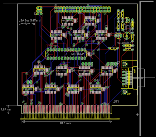
However, I have learned that there is a easier way to go about it. It turns out that the CPU outputs a couple of bits of information concerning the state of the prefetch queue on two of its pins (QS0 and QS1), allowing us to distinguish between 4 possible operations which can occur on each cycle: first byte of opcode removed, subsequent byte of opcode removed, queue emptied and no change. Being able to read that information (along with exactly what the bus is doing) would make figuring all this out much easier. I didn't want to use a logic probe to do this because (among other reasons) I wanted to be able to set up a large number of experiments and run them all automatically. So instead I have designed an ISA card which (completely transparently to the PC or XT it's plugged into) uses a microcontroller to sample the state of many lines and transmit the results to another PC over a serial connection.

Compared to a real logic probe we can only sample a few lines at once, only gather a couple of KB of samples at once and can't sample very often (I think 4.77MHz should be possible), but the experiments I care about are all deterministic so we can just repeat the experiment enough times to gather all the data I want. Here's the schematic for the bus sniffer and here's what the board layout looks like:

I've ordered a PCB from BatchPCB (the first time I've actually had a PCB professionally made) so we'll see how it works!

LED strobe and spinning disc

Thursday, October 4th, 2012

My son's Elenco Snap Circuits Jr. SC-100 toy came with a spinning disc that demonstrates stroboscopic behavior when accelerating or decelerating under a fluorescent light. I built my own LED strobe with adjustable frequency and duty cycle to make the effect a bit more visible. In the following video you can see what happens as the duty cycle is adjusted:

The circuit is too simple to show a schematic for - just a LED with current limiting resistor and three potentiometers connected to an Arduino. The clever bit is the Arduino program. Also, because I needed to be able to tune the frequency quite precisely, I used two potentiometers for the frequency - one for coarse adjustments and one for fine. Only the top 6 bits of the coarse potentiometer's measured value are used (otherwise the fine potentiometer would be useless due to the jitter). The remaining 10 bits come from the fine potentiometer, yielding a theoretical 16 bits of frequency resolution, giving a range of about 3.8Hz to 250KHz.

The video would probably come out better if I connected multiple LEDs to the output, but I only had one white LED to hand.

Zoomable family tree

Wednesday, October 3rd, 2012

There seem to be lots of people on the internet who don't really understand evolution. You can tell who they are because they ask things like "If people evolved from monkeys, why are there still monkeys?" and claim that there are things called microevolution and macroevolution which are qualitatively different. Sometimes this happens because people perceive there to be a conflict between their preconceived beliefs and the theory of evolution. Sometimes though it's just that they're taught by people who have such perceptions, which is a bit of a tragedy because a poor quality of teaching will lead to these students not being able to contribute to science in the future.

Without pretending to have any answers for the more fundamental problem of bad teaching, I do have an idea which could help people get an intuitive understanding of how evolution works.

Really what evolution says is that there ultimately there is a single family tree - we're all related if you go back far enough. Also, the blueprints for our bodies are not engraved in some unalterable stone tablet sealed in a cryogenic vacuum somewhere - they're stored as atomic-scale patterns inside our warm, wet cells and therefore change from time to time (albeit very slowly by the timescales we're used to).

So what I'm imagining is a phylogenetic tree viewer with a twist - you can zoom into a phylogenetic tree, and if you zoom in far enough you can see individuals and the parent-child relationships between them, like a normal family tree. Individuals would actually be shown as what typical individual of that lineage would have looked like (possibly with typical random variations). But these pictures would be stored in some kind of vector representation so that one could be morphed into another gradually. The point is that no matter where you zoom in, there's no place you can find where the children don't resemble their parents. You'd also be able to get an intuitive understanding of the process of speciation by seeing how a single species lineage splits into two, but on the level of individuals there's no one individual that you can point to that marks the point at which the species diverge.

By zooming in right at the top of the tree you'd be able to see (a theory of) abiogenesis (the first point at which information was passed on from parent to child).

A simple version of this program (just including a tiny minority of species) would be relatively easy to create and could still fulfill the basic educational possibilities. But the biologists collaborate and the more data that the program was fed, the more interesting things could be done with the result. Ideally it would be made as accurate as possible according to current best theories. Of course, a huge amount of the data is currently unknown and would have to be synthesized (at high zoom-in levels, almost all of the details would need to be made up). So if the program is used for scientific purposes it would be good to have some way to visualize which aspects of the image are accurate according to current best theories and which aspects were synthesized.

The data that's added to the program need not all be biological in nature - people could add their own family trees (and even those of their pets) as well (though reconciling low-level actual data with synthesized data could be tricky).
British TV is so civilized

Tuesday, October 2nd, 2012

I tried out the iPlayer for the first time last night (at the time of writing) to watch the first episode of the new series of Doctor Who, which I had missed the beginning of due to having to put the children to bed. On going to the BBC website it was just three clicks - one to start "watch live", one to restart the current program and one to maximize the window. And there was negligible buffering time, and it was higher definition than standard definition TV! I was very impressed. It was a great episode too - most of the Dalek episodes suffer from massive unexplained plot holes, but this one was quite well thought out.

Some of the US networks have streaming sites, but they all have adverts, the quality is worse than standard definition TV and new shows usually aren't available for a day to a week after they air. Plus a year's basic cable subscription costs more than a year's UK TV license.

Adventures in CRTC lockstep

Monday, October 1st, 2012

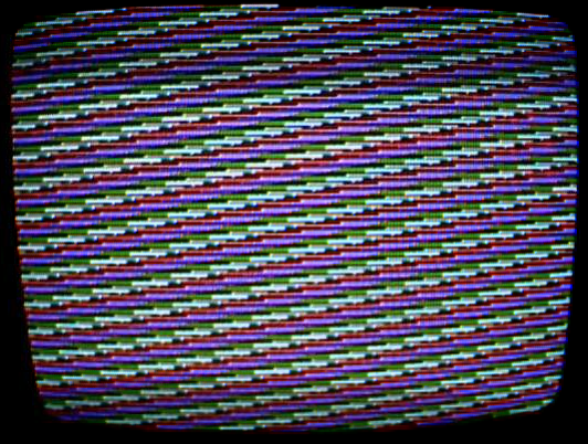
Once I had achieved CGA lockstep, I tried some test programs. This image was made by cycling through the possible palette registers as quickly as possible (i.e. it's running a big unrolled loop of "INC AX; OUT DX,AL" to the palette register):

That worked great, except that in making it I noticed that the pattern wasn't always starting the same way - half the time the first visible scanline had different set of colours. Somehow a bit of state was leaking through my lockstep routine!

After a while I figured out that it was due to the way I was getting the CRTC into lockstep with the CGA and CPU. The smallest frame that the 6845 CRTC can do is two character clocks (1 character by 2 scanlines - a 1 scanline high frame doesn't work with that CRTC). I thought I could get around this by going into high-res mode - then 1 character clock is 1 hchar so a frame would be 1 lchar and we'd be in a known place in the frame once we were in a known place in the CGA cycle.

Have you spotted the problem yet? The problem is that I don't know what the phase relationship is between the CGA clock and the CRTC clock - the first hchar of the frame could be the left or the right hchar within the lchar! And in fact, which it turned out to be was decided at random on startup.

With a bit of fiddling I eventually came up with a way to get the CRTC into lockstep as well. The trick hinges on the fact that if we set up the CRTC parameters so that one of the scanlines is displaying a normal visible image and one is overscan, we can tell which scanline is which by reading the display enable bit of the CGA status register. Then we delay an odd number of lchars if the display enable bit is set one way and an even number of lchars if it's set the other way (it doesn't matter which is which). Because we want to keep the CGA and CPU in lockstep as well, the difference in the codepath lengths must also be a multiple of 3 lchars, so delaying for X lchars one way and X+3 the other works fine.

That's about all there is to it. The full lockstep routine is on github. Once lockstep is entered it'll persist until you wait for a time that depends on an external event (such as reading from disk/serial/parallel/ethernet/joystick or waiting for a keystroke). That doesn't mean that lockstep mode games and trackmos are impossible, though. The keyboard can be read by polling (pretty much all PC software directly or indirectly uses an interrupt for keyboard access but it isn't compulsary and I've done it by polling a few times). You just have to make sure the code paths are the same length no matter whether a key was pressed or not and no matter which key was pressed if there is one, which can be done by adding suitable delays. Disk access is a bit more difficult, since there's going to be a DMA bus access at some unpredictable point, and after it's happened you'll be out of lockstep. I think the solution is to HLT after the disk access is complete and restart execution on a timer interrupt. In the event that lockstep between CGA and PIT isn't possible, regaining lockstep once the timer interrupt has occurred should be possible by delaying for N ccycles for some N between 0 and 15 and a CGA memory access. Another possible way is to make sure the CPU is running code that is either:

  1. BIU-bound with no wait states, or
  2. that is EU-bound and never exhausts the prefetch queue

for the entire time that the accesses might be happening. That way the time taken to run the code doesn't depend on exactly when the accesses occur.