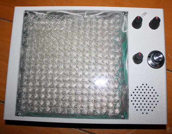
Inspired by Andre' Michelle's Tone Matrix flash applet I decided to make a physical version - i.e. a box with buttons, flashing lights and knobs to turn. I wanted 16x16 - the Bliptronic 5000 just doesn't have enough lights. All the existing 16x16 equivalents were more money than I wanted to pay: A Tenori-on costs something like $1000. Four Bliptronic 5000s cost $200. A monome two fifty six costs $1400. I was thinking more along the lines of $50. Besides which, I thought to myself, it would be fun to make it myself.
I decided to base it around the ATmega328 microcontroller used in the Arduino, after reading how easy it is to get started hardware hacking with the Arduino. Yes, I know a Cortex M0 is a cheaper and more powerful chip, but I didn't know about these until I'd already started with the ATmega328. Also, they're more difficult to solder.

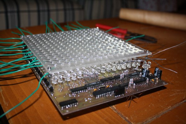
Because of my assembly programming roots, I wanted to push the CPU to its limits. Sketching out the core audio and video assembly routines, I realized that with the Arduino's 16MHz clock rate, I could do 16 channel PWM audio at a sample rate of 15.625KHz (i.e. a sample every 1024 cycles) with a 256-element 8-bit waveform and arbitrary volumes and frequencies for each channel. At the same time I could control a 16x16 LED matrix with a refresh rate of 61Hz (line rate of 976Hz) with each individual LED having an independent brightness (duty cycle of 0-16 sample periods per frame, i.e. up to 1/16 in 1/256 increments) using 32 bits of shift registers and the SPI lines (at maximum speed it takes a significant number cycles to output so many bits, so this is interleaved with other code). Unfortunately (because of the large gamma of LEDs) only a few of these are distinguishable. With all of this going on in the background (written in heavily optimized assembly language) I still had enough spare CPU cycles to do some interesting foreground things.

The next problem was how to make the switch matrix and LED matrix. I thought about buying 4 Bliptronic 5000s and tearing them apart, or using sixteen Sparkfun 4x4 button pads with PCBs, but both of those options cost more than I wanted to pay. The cheapest high-brightness LEDs I could find cost $0.06 in quantity from Mouser, giving a screen cost of $15.36 - much more like it. (Even cheaper prices are possible in greater volumes from Transistor Parts Wholesale). I think this is the cheapest way of making a 6"x6" screen.

I had trouble thinking of a way to set up 256 switches over the LEDs without obscuring them or spending too much, until I remembered an effect I had noticed messing about with transistors years ago - you can make a touch switch out of a couple of transistors arranged in a Darlington configuration. I could arrange them in a matrix like the LEDs so that the only per-switch cost was a couple of small sections of wire. This could be threaded through an acrylic sheet which would serve a dual purpose - to diffuse the LEDs and to hold the switch wires. I originally thought I would have 4 solder connections to the PCB per switch, but then I realized that that would be too difficult to solder and that it would be better to just connect my switch matrix at the edges.

The row strobes used for the switches are the same as the ones used for the LEDs, and the column strobes are accomplished with a couple of 8-bit analogue multiplexers, so that only two Darlington pairs are needed for the entire matrix (the final thing includes a third for a "menu" switch). One tricky thing here turns out to be the capacitance - since the finger resistance is about 10 megaohms and we move on to the next switch 15,625 times per second, we need a capacitance of no more than 6pF, which one gets from having just a few centimeters of wire in close proximity. Fortunately that's just for between the multiplexer and the Darlington pair - the switch matrix itself only changes configuration 976 times per second so we can get away with a larger capacitance. Even so, I think this is at about the limit of practical resolution for such a matrix. It proved necessary to put a capacitor between the base of the Darlington pair and ground to counteract the admittance of the switch matrix and reduce its sensitivity.

I used a double sided circuit board (in order that I could have LED row wires on one side and column wires on the other), but I think if I were doing it again I'd use a single sided board and just connect the columns by soldering the LED anodes to straight pieces of wire laid across the top of the board. Between aligning the two sides correctly, doing very fiddly soldering under the components on the top side, making lots of vias and not being able to test most of the board until almost everything was soldered (due to some of the component legs acting as vias) it was more trouble than it was worth.

For debugging purposes, I made a connector so that the device could be connected via an Arduino and a USB port to a computer. There is essentially a "non stop" debug interface built into the program - as it's running, one can send commands over the ATmega's UART to peek and poke memory.

The sound quality isn't great at the moment - it was okay on the breadboard but the breadboarded version of the circuit had a "screen" of only 4 LEDs. With 256 LEDs the ripples on the power supply are much bigger and there's a lot of noise on the speaker when lots of the pixels are lit. I did have some decoupling capacitors in the circuit but I drastically underestimated the amount of capacitance I would need - I'll replace the capacitors with larger ones after my next Mouser order.

The final design has 4 potentiometers: tuning, volume, decay/sustain and tempo.

The software I wrote for it has lots of features:
- Random mode: after each cycle through the pattern, extinguish one LED at random and light another at random. This keeps the pattern varying.
- Game of Life mode: after each cycle through the pattern, transform the pattern according to Conway's rules.
- Various waveforms: choose from sine wave, square wave, triangle wave (which unfortunately sounds indistinguishable from the sine wave) or two different types of random noise. There are also a couple of different waveform editors so you can make up your own.
- Tuning editor: the default scale is pentatonic but you can change it to use whichever frequencies you like.
- Overrides for decay, tempo and tuning so they can be set via either digital or analogue controls.
- Microtone mode: sets the matrix up as a 256-key keyboard spanning 7.5 octaves with a 34-TET tuning. LEDs corresponding to the notes of the C major scale are lit (which makes a pretty pattern). Because of the way the switch matrix works, only chording within a row or a column is possible without introducing spurious notes.
- Saving and loading patterns, waveforms, tunings and other settings to/from EEPROM. Unfortunately there is a bug in the software at the moment which causes it to crash after saving.
- Multi-pattern mode: loads a new pattern from EEPROM each time the current one finishes.
- Sync in and sync out sockets: I believe these should be compatible with those on the Bliptronic 5000, but I don't have one to try it out with.
- Ability to have less than 16 beats before repeat (for making rhythms with different time signatures).
- Just for fun, a red/green/blue LED triplet. This displays a hue corresponding to the beat currently being played within the pattern. It seems totally frivolous, but was quite handy for debugging this problem when the program was so broken that the serial code didn't even work.

There are a few more that I've thought of but haven't implemented yet. Almost half the flash is unused currently - enough to add a few games as well.

The machine runs great on 4 AA batteries (6.52V according to my multimeter) or from a 5V supply. I think the ICs are rated up to 15V or so, but the LED current limiting resistors would need to be increased to use a higher voltage.
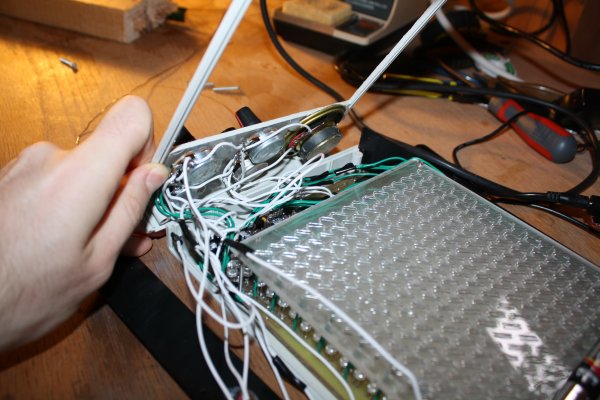
One tricky thing about making this is threading all the wire through the acrylic sheet - I used fairly thick wire (22 AWG) for strength so I had to be careful to avoid kinks and make sure the wire was tight each time. Using thinner wire would be easier but flimsier. I imagine that it could be mass produced more easily using techniques similar to making a double sided PCB (i.e. using tracks and through-hole plated vias instead of a solid piece of wire).
In the end the parts cost for this adds up to $64.83 (not counting time, broken tools and supplies like solder, toner, paper, acetone, steel wool, glue and ferric chloride), though not all of the parts I actually used were bought new (I salvaged the speaker and a capacitor from an old alarm clock, for example). It could probably be mass produced for significantly less (particularly the case I imagine).
The schematics, source code, PCB layout and parts list are available here. If you make a copy or derivative I'd love to hear about it.
AMAZIIING! I want this now. D:
Thanks, Taina! I thought about making a bunch of them, but making this one took rather longer than I thought it would. So unless there's enough interest for a mass-production run, I think it's going to be a one-off (or few-off, if other people decide to build copies).
Have you thought about producing them for people with sensory processing problems? There are a few individuals that I know, who have autism, who would really love this thing. Looks great anyway mate. Kudos
Thanks, Dom. That's a market I hadn't considered!
[...] Jenner] pulled off something amazing with this Physical Tone Matrix. He wanted to build a physical version of a flash applet he had seen. Two layers make up the main [...]
I saw the flash version and thought it was awesome... then I saw this one. Blew my mind. Keep up the good work!
I love it! A diy Tenori-on! That's actually really impressive!
No midi out? Would be easy to augment with a midi out.
It is very cool...but the 2-bit minimalist hipster blips get old really fast from a musical perspective. Just speaking as a musician who would try and use this as a tool, at this stage, you really couldn't.
Put midi out on it and hook it up to a real software synth and it would be a serious controller, or else bump up the sound generation quality by a huge factor.
Very impressive and has huge potential. Awesome job.
Thanks! Yeah, I think I could probably add MIDI pretty easily - I just have no reason to at the moment, since I'm not a musician and don't have a proper synthesizer to hook it up to. If I was redesigning it for mass production, though, I'd definitely add this. I'd also fix the audio quality issues (using a microcontroller that was capable of more sophisticated synthesis than bloops and bleeps).
This is amazing! I was wondering if you, or some links you had could shed some light on the production of the screen. It's such a great design!
Yeah, I'll write another post on the screen.
Edit: here it is.
Very amazing indeed! I have thought about this too, ever since I used the tone matrix flash applet the first time, but unfortunately I lacked the know-how to build a cheaper one than Monome or even the 4xBliptronic-set.
Thank you for making and documenting this, and thanks even more for the more detailed post on the screen production!
[...] Reenigne blog Stuff I think about « Physical tone matrix screen construction details [...]
I was inspired and made this http://www.blergo.com/games/play/blergo-beats
Cool! :-)
[...] a virtual version of my physical tone matrix, implemented in Flash, so you can play along at [...]
[...] been thinking about how to create the interval bars instrument/toy as a sort of sequel to the physical tone matrix. Here’s some of the design space I’ve [...]
[...] an update to yesterday’s post on the Tone Matrix, here’s a very stylish realization from the Reenigne blog. Featuring 16×16 LED lights (just like the Flash app), the same number of switches (using [...]
[...] sound so useful except maybe as a source of parts for fancier projects … or … trigger? controller? [...]
[...] tone_matrix - the code for my physical tone matrix. [...]
[...] of these waveforms at some particular frequency and volume. This is almost exactly the way that my physical tone matrix renders [...]
[...] does for fun. At least, that’s one of the things he does for fun, when he’s not building new electronic music toys for his children, or writing a cycle-exact 8088 emulator, or just generally visiting every single hackerspace in a [...]
if you would sell these i would buy 2 of these
Andrew,
I found out about the tonematrix only about a week ago. This morning, for some reason, I woke up with this genius idea of creating a physical version of it. I was a little dismayed to find out someone had beaten me to it, although the idea I had in my mind is vastly different from your interpretation (which I love!).
I thought maybe I could bounce my idea off of you and get some feedback on it. Would you be able to e-mail me at the address I provided? (Grad school has made me terrified to share ideas with the general public before I've had a chance to pursue them, haha.)
Hey I really like what you did with the tone matrix and me and my roommate are working on a project to build 1 that is life size an interactive. Is there a way we can contact you to get ideas on how you built your version so we can incorporate it in our full scale version?
Yes, my email address is andrew@reenigne.org . I just sent you email.
[…] position gets advanced each sample (direct digital synthesis - similar to that which I used in the Physical Tone Matrix). These frequency values are modified right in the code itself during runtime (self-modifying […]